-
Voltage and Current: Motors (2019)
-
 Introduction: Fan
 -
Failed Motor Circuit: Insufficient Voltage
-
 Check Your Understanding: Failed Motor Circuit
 -
Mini-Project: Current Investigation
-
 Upload Photo: Measuring current using a multimeter
 -
Check Your Understanding: Current Investigation
-
Mini-Project: Larger Battery
-
Upload Photo: Creating a Larger Battery
-
Check Your Understanding: Larger Battery
-
Motor Direction
-
Fuses
-
Upload Photo: Using a Fuse
-
Check Your Understanding: Fuses
-
Rechargeable Batteries
-
Check Your Understanding: Rechargeable Batteries
-
Project: Fan
-
 Upload Video: Fan
 -
Upload Block Diagram: Fan
-
Fuses
Mini Project Motor Box with Fuse

High current levels in circuits can be dangerous, and also can damage components in a circuit. There are times where component replacement can be very costly.
To prevent damage to components from high voltage or current, a device called a Fuse can be added inline with circuits. A fuse typically is a metal wire or strip that melts when too much current is flowing through the circuit.
In this project, we will add a fuse to the Motor Box circuit.
Find the following components in your kit:
-
 Fuse and Fuse holder with Leads
-
 Wire cutter and wire stripper
-
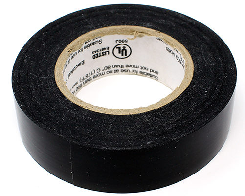 Electrical Tape
-
 Two Coin Cell Batteries
-
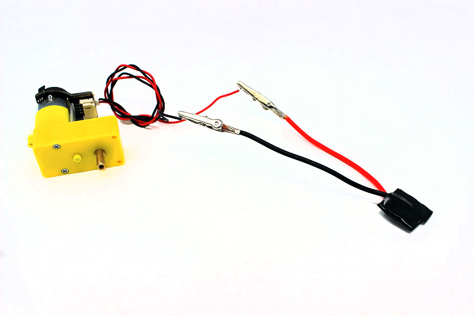 The Motor Circuit from the previous lesson
-
 Digital Multimeter
-
 Alligator Clip
-
 Wire
Wire
-
 Alligator Clip Crimper
-
 Wire Stripper

Modify the Motor Box to add in the Fuse. Begin by cutting and stripping the Fuse holder wire toward the center of the loop, and attaching an alligator clip to one end of it. Also create a black wire with one stripped end and one end with an alligator clip.
Follow along with this module to prepare wires with alligator clips.
To begin crimping clips, you will need the following:
-
Alligator Clip
-
Wire
-
Alligator Clip Crimper
-
Wire Stripper
Take the end of the wire, and make sure there is enough conductor exposed to attach the connector -- about 1 cm, or half an inch is good for this type of clip.


Insert the exposed conductor through the small loop on the back of the alligator clip.
Note: If the connection is too loose, strip off some more of the insulator and fold the conductor together to create an extra "thick" wire for the alligator clip slot.

Tip: Twist the ends of the conductor strands so they stay together more easily.

Insert the loop + conductor into the slot on your crimper that matches the size of the loop.
Firmly squeeze the handle of the crimper to press the loop closed around the conductor. Many crimper designs will not open back up until you have squeezed far enough -- if the crimper won't open, keep squeezing until it does.

Tip: You can squeeze harder if you grip toward the ends of the handles.

Tip: If you really need the crimper to open early, there is usually a small release latch inside the handle.

To ensure the fit is good on all sides, rotate the connector 90 degrees, and squeeze the handle closed again.

The alligator head connector should now be securely attached to your wire!

Test the continuity of the fuse with multimeter to see that it lets electricity through. Feel free to also check the black wire you made.
Follow along with this module to refresh your memory on how to test continuity.
To begin testing wires, you will need the following:
-
Digital Multimeter

A multimeter can be used to test for an unbroken electrical connection between two points. Something with no breaks is called "continuous", so this process is called "continuity" testing.

The continuity testing function of the multimeter tests for electrical continuity between two points that you touch the multimeter's leads to.
Tip: If there is a continuous connection, the multimeter will make a beep sound, so the icon for this mode usually looks like a "sound waves" symbol.
The continuity tester does not work on circuits that have power running through them. Disconnect power from the portion of the circuit you are testing and test the parts individually. The multimeter may be damaged if you attempt to use this feature on a powered circuit.

Plug the black lead of the multimeter into the COM terminal.
Plug the red lead of the multimeter into the terminal with one of the following icons next to it:
-
 Continuity Symbol
-
 Resistance (Ohms) Symbol
-
 Voltage (Volts) Symbol
-
 Diodes Symbol
Tip: The continuity test feature is electrically similar to several other multimeter functions, so it usually shares a plug and a spot on the dial with one of them. Different multimeters have it share with different modes.

Turn the dial to the connectivity testing setting.
Some multimeters, like the orange one shown, have multiple functions on a dial setting. You may need to press the FUNC or function button to switch the multimeter to the connectivity testing setting. Look for the connectivity symbol on the screen of the multimeter.

Touch the metal parts of the multimeter leads together. The multimeter should make a sound while they are in contact (because the two leads are electrically connected to each other).
Touch the two leads to the ends of the wire you want to test. If you hear a sound, it means that there is a continuous electrical path between those two points.

Attach the postive side of battery to the stripped wire end of the Fuse holder lead. Connect the black wire to the negative side of the battery. Electrical tape works well for attaching to the battery.

Complete the circuit by attaching the alligator clip of the Fuse holder lead to the motor lead.

Measure the current (amperage) with the multimeter. What is it reading?
Follow along with this module to refresh your memory on how to measure current.
To begin testing wires, you will need the following:
-
Digital Multimeter
A multimeter can be used to test for an unbroken electrical connection between two points. Something with no breaks is called "continuous", so this process is called "continuity" testing.
The continuity testing function of the multimeter tests for electrical continuity between two points that you touch the multimeter's leads to.
Tip: If there is a continuous connection, the multimeter will make a beep sound, so the icon for this mode usually looks like a "sound waves" symbol.
The continuity tester does not work on circuits that have power running through them. Disconnect power from the portion of the circuit you are testing and test the parts individually. The multimeter may be damaged if you attempt to use this feature on a powered circuit.
Plug the black lead of the multimeter into the COM terminal.
Plug the red lead of the multimeter into the terminal with one of the following icons next to it:
-
Continuity Symbol
-
Resistance (Ohms) Symbol
-
Voltage (Volts) Symbol
-
Diodes Symbol
Tip: The continuity test feature is electrically similar to several other multimeter functions, so it usually shares a plug and a spot on the dial with one of them. Different multimeters have it share with different modes.
Turn the dial to the connectivity testing setting.
Some multimeters, like the orange one shown, have multiple functions on a dial setting. You may need to press the FUNC or function button to switch the multimeter to the connectivity testing setting. Look for the connectivity symbol on the screen of the multimeter.
Touch the metal parts of the multimeter leads together. The multimeter should make a sound while they are in contact (because the two leads are electrically connected to each other).
Touch the two leads to the ends of the wire you want to test. If you hear a sound, it means that there is a continuous electrical path between those two points.
Explanation

Fuses are often used to robotics to prevent damage to the components in the system. You may see devices that are similar to fuses called a Circuit Breaker.
Much like the metal-wire type fuses we learned about earlier, Circuit Breakers detect the voltage or current within the system and will open a mechanical switch that opens the circuit so that the circuit no longer has voltage. Electrical boxes in homes typically have these types to protect your home.
