-
Voltage and Current: Motors (2019)
-
 Introduction: Fan
 -
Failed Motor Circuit: Insufficient Voltage
-
 Check Your Understanding: Failed Motor Circuit
 -
Mini-Project: Current Investigation
-
 Upload Photo: Measuring current using a multimeter
 -
Check Your Understanding: Current Investigation
-
Mini-Project: Larger Battery
-
Upload Photo: Creating a Larger Battery
-
Check Your Understanding: Larger Battery
-
Motor Direction
-
Fuses
-
Upload Photo: Using a Fuse
-
Check Your Understanding: Fuses
-
Rechargeable Batteries
-
Check Your Understanding: Rechargeable Batteries
-
Project: Fan
-
 Upload Video: Fan
 -
Upload Block Diagram: Fan
-
Failed Motor Circuit
Mini Project Larger Battery
The circuits that you have been building have used a single battery with 3.3 volts. For this project, we will combine two batteries together to create a larger battery.
 Block diagram: Motor with a larger battery
Find the following components in your kit:
-
 Two Fresh Coin Cell Batteries
-
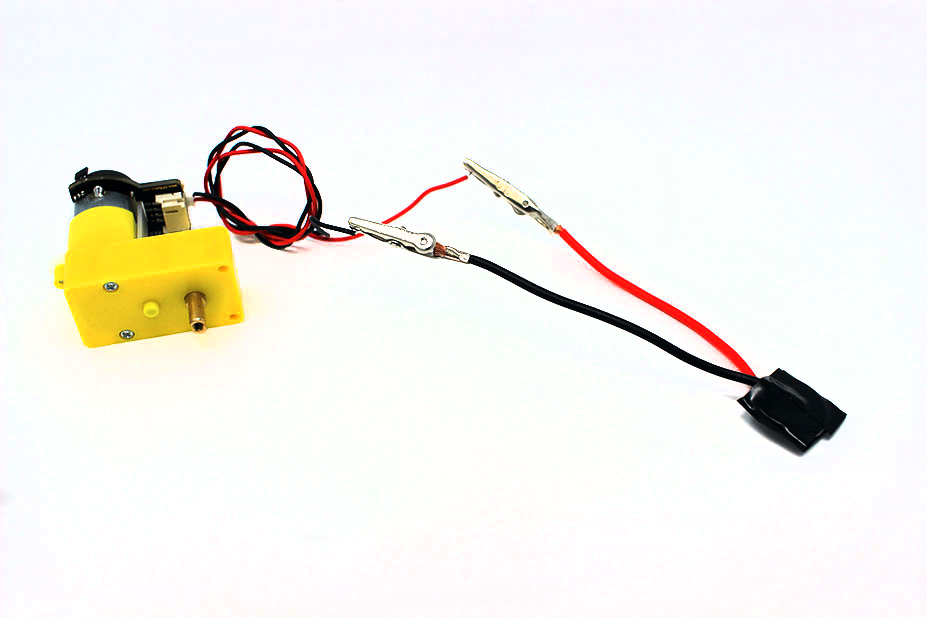 The Motor Circuit from the previous lesson
-
 Digital Multimeter

Build this circuit shown here.

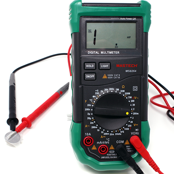
Use a multimeter in voltage mode to check the voltage across the motor.
Use the module below if you need a refresher on how to measure voltage using a multimeter.
To begin testing wires, you will need the following:
-
Digital Multimeter
Multimeters measure voltage differently for Direct Current (DC) Circuits and Alternating Current (AC) Circuits. On a multimeter these setting are shown with different symbols:


AC voltage can be very dangerous (especially the main voltage out of outlets on a building’s wall) and great care must be taken when measuring it with a multimeter. If you feel like you must test or measure AC, it is recommend you get a non-contact tester rather than use a digital multimeter.

Depending on the multimeter you have you may have one setting or many different settings for DC Voltage.

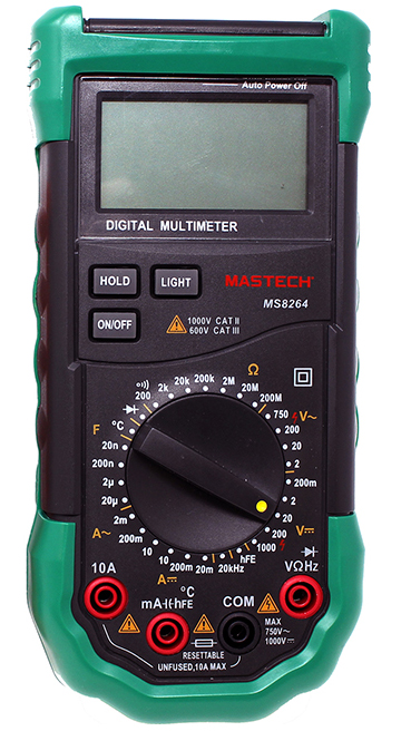


When measuring voltage make sure your probes are plugged into the correct ports. The Black Probe should be in "COM" or common and the Red Probe should be in the Red Port with the Voltage symbol (V)
When measuring voltage in a circuit it is always useful to know the voltage of your power supply, frequently with DC circuits this power supply is in the form of the battery.
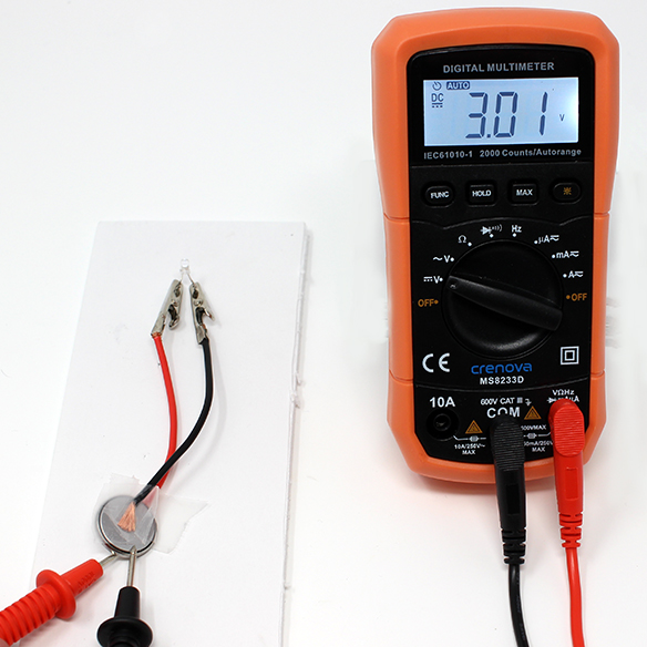

The multimeter can be used to test different parts of the circuit in a practice called nodal analysis. By measuring the voltage across the circuit, we can see how much voltage each component requires. In a very simple circuit such as an LED in series with a battery, the LED can be used to measure how much voltage the LED is using. This voltage is referred to as voltage drop.
Measuring the voltage drop of component in a circuit, requires the circuit to be connected. With the LED bright and lighting up probe both legs with the multimeter. (Place the red probe on the longer leg of the LED to measure positive numbers)
This LED is using 2.74 Volts of the available 3.01 Volt supply to illuminate.
Check Your Understanding


What happens?
The motor spins faster than the previous circuit. The voltage across the motor should be larger than the previous circuit.
Try It: Stall the motor
What happens if you hold the spinning end now?
Explanation
The circuit now has more voltage! There is enough strength to overcome your fingers trying to stall the motor. Combining the two batteries increased the amount of voltage that is in the circuit. This allows there to be more voltage to power the motor.
Larger batteries typically are formed from multiple smaller batteries in series. For instance, this A23 battery is actually made up of several coin cell batteries:

Measure the current.Disconnect an alligator clip from one of the motor leads, and use your multimeter to measure the current going through those two points.

How much current is going through the circuit now? Is it larger or smaller than the previous, single battery circuit? With two batteries now, there is not only more voltage, but more current.
Safety: Higher voltage and higher current can be dangerous. Voltage levels higher than 50 Volts can carry a dangerous, or even fatal, amount of current!