-
Voltage and Current: Motors (2019)
-
 Introduction: Fan
 -
Failed Motor Circuit: Insufficient Voltage
-
 Check Your Understanding: Failed Motor Circuit
 -
Mini-Project: Current Investigation
-
 Upload Photo: Measuring current using a multimeter
 -
Check Your Understanding: Current Investigation
-
Mini-Project: Larger Battery
-
Upload Photo: Creating a Larger Battery
-
Check Your Understanding: Larger Battery
-
Motor Direction
-
Fuses
-
Upload Photo: Using a Fuse
-
Check Your Understanding: Fuses
-
Rechargeable Batteries
-
Check Your Understanding: Rechargeable Batteries
-
Project: Fan
-
 Upload Video: Fan
 -
Upload Block Diagram: Fan
-
Failed Motor Circuit
Mini Project Current Investigation
Let’s take a deeper look into what current is, and what it has to do with voltage. To do this, we will use the multimeter to measure the current in our motor circuit.
 Block diagram: Multi-meter connected to circuit

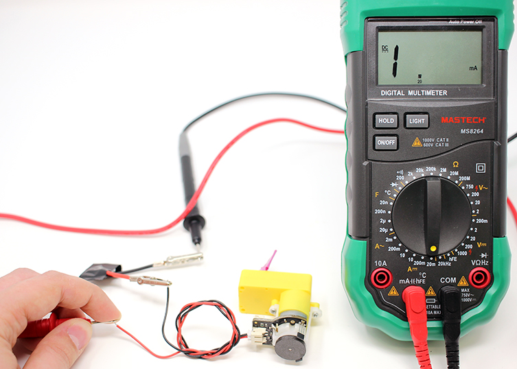
Disconnect an alligator clip from a motor lead so that the battery doesn’t get used up. Go through the following section to learn how to use multimeter to see the amount of current is going through the motor.
To begin testing your circuit, you will need the following:
-
 Digital Multimeter
Multimeters measure current differently for Direct Current (DC) Circuits and Alternating Current (AC) Circuits. On a multimeter these setting are shown with different symbols. Some multimeters have a setting that measures both AC and DC current. Current is measured in a unit called Amperes, more commonly called Amps. Measuring amperage can damage a multimeter. Check the bottom ports of your multimeter to see the maximum input the multimeter can handle.


AC current can be very dangerous (especially the main voltage out of outlets on a building’s wall) and great care must be taken when measuring it with a multimeter. If you feel like you must test or measure AC, it is recommend you get a non-contact tester rather than use a digital multimeter. Any electrical device used on a house wiring circuit can, under certain conditions, transmit a fatal current. While any amount of current over 10 milliamps (0.01 amp) is capable of producing painful to severe shock, currents between 100 and 200 mA (0.1 to 0.2 amp) can be lethal with a high voltage (40+ Volts).

Depending on the multimeter you have you may have one setting or many different settings for measuring Current.

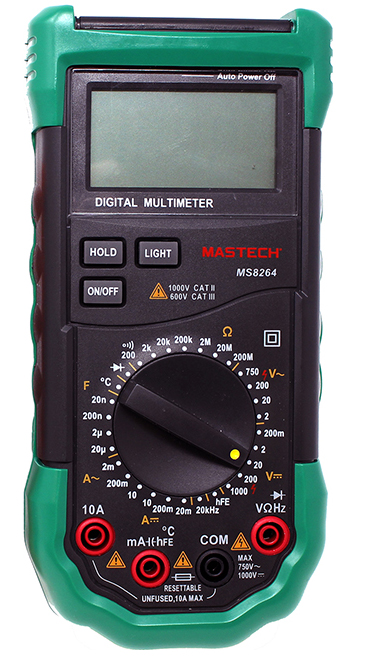


When measuring Current, make sure your probes are plugged into the correct ports. The Black Probe should be in “COM” or common and the Red Probe should be in the Port with the Current symbol (A).The following example will use an LED, LEDs do not draw high amount of current so the measurement will be taken using the mA port.
The multimeter can be used to test current going through parts of the circuit between components. Measuring the current between components requires the circuit to be open, or disconnected. The multimeter will act as a "wire" in your compleated circuit.

Check Your Understanding


Measure the current that is going through the alligator clip and the motor lead using the multimeter.
It should read somewhere around 70 μA (nano Amps) or 0.07mA (mili Amps). This circuit has a brand new battery and the current is 0.08mA. Record this value in your log or keep this in mind for the next section.
Explanation What is Amperage?

Amperage is a measure of electrical current flow, also called amps for short. An Amp is a measurement of the number of electrons in a conductor flowing past a certain point in a given amount of time. Think of a highway and you want to measure all the cars passing exit 4 past exit 5 in one hour. In a circuit, this measurement would be looking over a small portion of a wire for a second.