-
Voltage and Current: Motors (2019)
-
 Introduction: Fan
 -
Failed Motor Circuit: Insufficient Voltage
-
 Check Your Understanding: Failed Motor Circuit
 -
Mini-Project: Current Investigation
-
 Upload Photo: Measuring current using a multimeter
 -
Check Your Understanding: Current Investigation
-
Mini-Project: Larger Battery
-
Upload Photo: Creating a Larger Battery
-
Check Your Understanding: Larger Battery
-
Motor Direction
-
Fuses
-
Upload Photo: Using a Fuse
-
Check Your Understanding: Fuses
-
Rechargeable Batteries
-
Check Your Understanding: Rechargeable Batteries
-
Project: Fan
-
 Upload Video: Fan
 -
Upload Block Diagram: Fan
-
Failed Motor Circuit: Insufficient Voltage
Mini Project Motor Strength
In this project, you will investigate how a motor reacts to being powered by the coin cell battery.
 Block Diagram: Motor connected to battery
Find the following components in your kit:
-
 A Fresh Coin Cell Battery
-
 A 6V motor with the red and black cable
-
 Electrical tape (any color)
-
 2 Wires: red and black
-
 2 Alligator clips
-
 Alligator Clip Crimper
-
 Wire Stripper

Create two wires: one red and one black. Each wire should have an alligator clip crimped onto one end.
Follow along with this module to prepare wires with alligator clips.
To begin crimping clips, you will need the following:
-
Alligator Clip
-
Wire
-
Alligator Clip Crimper
-
Wire Stripper
Take the end of the wire, and make sure there is enough conductor exposed to attach the connector -- about 1 cm, or half an inch is good for this type of clip.


Insert the exposed conductor through the small loop on the back of the alligator clip.
Note: If the connection is too loose, strip off some more of the insulator and fold the conductor together to create an extra "thick" wire for the alligator clip slot.

Tip: Twist the ends of the conductor strands so they stay together more easily.

Insert the loop + conductor into the slot on your crimper that matches the size of the loop.
Firmly squeeze the handle of the crimper to press the loop closed around the conductor. Many crimper designs will not open back up until you have squeezed far enough -- if the crimper won't open, keep squeezing until it does.

Tip: You can squeeze harder if you grip toward the ends of the handles.

Tip: If you really need the crimper to open early, there is usually a small release latch inside the handle.

To ensure the fit is good on all sides, rotate the connector 90 degrees, and squeeze the handle closed again.

The alligator head connector should now be securely attached to your wire!

Using electrical tape, connect the open end of the red wire to the positive side of the battery, and the open end of the black wire to the negative side of the battery.

Connect the alligator clip of the red wire to the red lead of the motor, and the alligator clip of the black wire to the black lead of the motor.

Use a multimeter in voltage mode to measure the voltage across the motor. Use the module below if you need a refresher.
Use a multimeter in voltage mode to measure the voltage across the motor. Use the module below if you need a refresher.
To begin testing wires, you will need the following:
-
 Digital Multimeter
Multimeters measure voltage differently for Direct Current (DC) Circuits and Alternating Current (AC) Circuits. On a multimeter these setting are shown with different symbols:


AC voltage can be very dangerous (especially the main voltage out of outlets on a building’s wall) and great care must be taken when measuring it with a multimeter. If you feel like you must test or measure AC, it is recommend you get a non-contact tester rather than use a digital multimeter.

Depending on the multimeter you have you may have one setting or many different settings for DC Voltage.

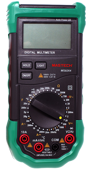
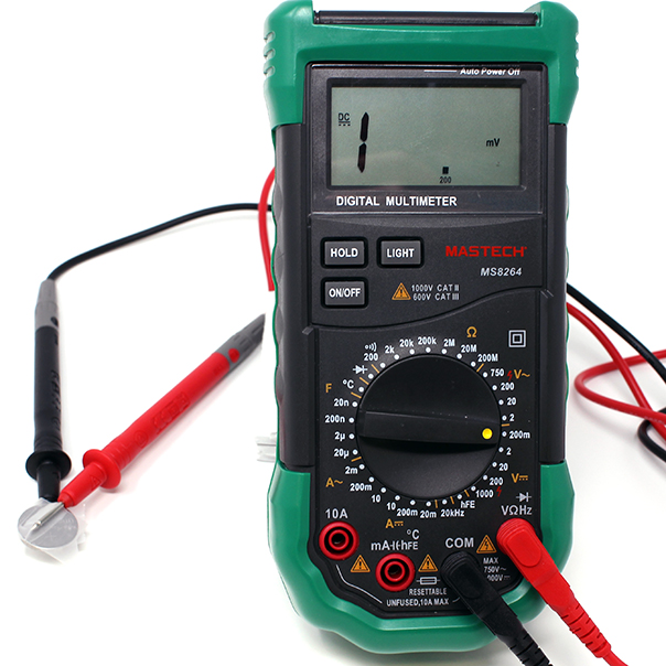


When measuring voltage make sure your probes are plugged into the correct ports. The Black Probe should be in "COM" or common and the Red Probe should be in the Red Port with the Voltage symbol (V)
When measuring voltage in a circuit it is always useful to know the voltage of your power supply, frequently with DC circuits this power supply is in the form of the battery.
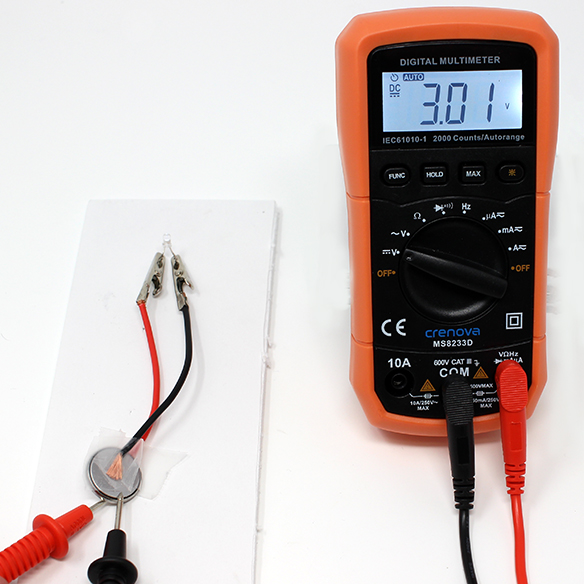

The multimeter can be used to test different parts of the circuit in a practice called nodal analysis. By measuring the voltage across the circuit, we can see how much voltage each component requires. In a very simple circuit such as an LED in series with a battery, the LED can be used to measure how much voltage the LED is using. This voltage is referred to as voltage drop.
Measuring the voltage drop of component in a circuit, requires the circuit to be connected. With the LED bright and lighting up probe both legs with the multimeter. (Place the red probe on the longer leg of the LED to measure positive numbers)
This LED is using 2.74 Volts of the available 3.01 Volt supply to illuminate.
Check Your Understanding


Disconnect an alligator clip so that you do not use up the battery.
Explanation
The battery sends electricity through the circuit to power the motor. Motors use up lots of energy, so you may notice that over a short amount of time, the motor will spin slower until there is not enough voltage to move the motor.
Try It: Stall the motor
What happens if you hold the spinning end?
 Reconnect the alligator clip, and use your fingers to hold the spinning brass end of the motor.
What do you think would happen if you were to use this amount of voltage on motors to try to move a robot?