Planned Spacing / Component Layout
Planning the E-Panel
Being able to plan out where components go in your system allows you to make sure that you have enough space and place them in such a way that it’s easier to work with and troubleshoot.
Sometimes you will be given a plan or layout, other times you will have to make your own. There are many ways that you can plan your electronics panel. A popular way is to use a CAD software like AutoDesk products or Solidworks to draw their plans.
![Dmitry G [CC BY-SA 3.0 (https://creativecommons.org/licenses/by-sa/3.0)], via Wikimedia Commons](https://s3.amazonaws.com/cs2n-curriculum/Electrical%20Foundations/Unit-6-E-Board/002-Planned-Spacing/1024px-Wiring_diagram_of_lighting_control_panel_for_dummies.JPG)
You can also do it without software simply by cutting out pieces of paper shaped like your components, and laying them out.

Mini Project Plan Your Layout
In this project, we will cut out pieces of paper the size of the components in our system to create a layout of our E-panel.
Find the following components in your kit:
-
 Arduino Uno
-
 Distance Sensor
-
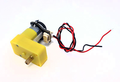 6V Motor
-
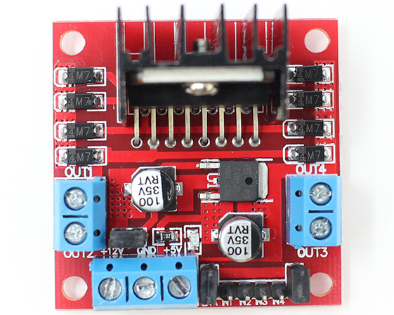 Motor Control Board
-
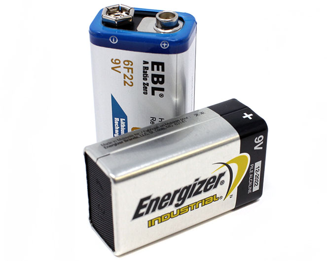 9 Volt Battery
-
 Scissors
-
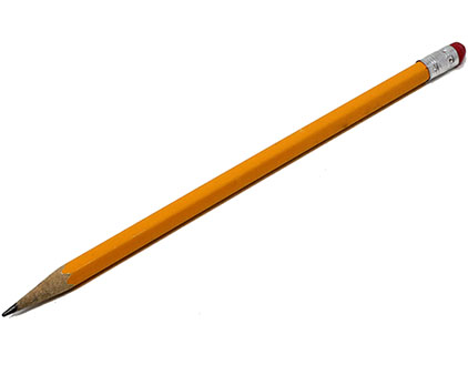 Pencil
-
 Paper
Paper
-
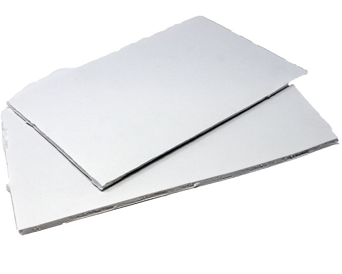 Foam Core
-
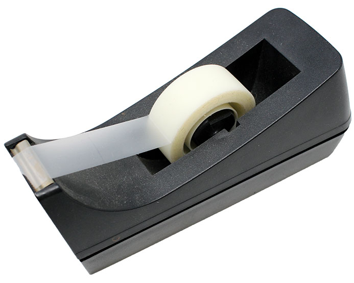 Tape
Tape

Using the sheets of paper and a pencil, trace an outline of the Arduino Uno, Distance Sensor, Motor, Motor Control Board, and the Battery.

Cut the shapes of the components using scissors.

- Arrange the components on the foam core board. The board will become your E-Panel. You will place the components on the E-Panel such that there is enough space for wiring and connections. If you’re unsure how to begin, start by placing the Arduino Uno cutout at the center of the foam board, and then place the other components around it.
- Tape the cutouts onto the board using the clear tape to make sure that they do not move.
You should now have an board with all of the components taped down.

You may want to treat the whole board as a block diagram. Drawing lines between connection components may help with organization.
What happens?
You should now have an board with all of the components taped down. To help with the next activities you may want to connect the components with lines, like a block diagram. Typically, planning the layout of an E-Panel involves more precise processes, and often involves the use of software (such as CAD software) to make an accurate visual.