-
Wiring and Circuits (2019)
-
 1. Introduction: Emergency Power Switch
 -
2. Simplest Circuit
-
 Upload Artifact: Photo of your simplest circuit
 -
 Check Your Understanding: Simplest Circuit
 -
Conductors and Insulators
-
Upload Artifact: Photo of circuit with conductor
-
Mini-Challenge: An Unwanted Shortcut
-
Check Your Understanding: Conductors & Insulators
-
3. Wires
-
Mini-Challenge: Wires
-
Upload Artifact: Photo of foamcore circuit
-
Check Your Understanding: Wires
-
4. Connectors
-
Mini-Project: Test your wire
-
Mini-Project: Electrical Tape
-
Upload Artifact: Photo of circuit
-
Check Your Understanding: Connectors
-
5. Simple Switches
-
Unit Project: Lightbox
-
Upload Photo: Lightbox
-
Simple Switches
Electrical systems should be set up so they can be turned on and off easily. This is helpful to people who use the system, but also important for safety.
On / Off Switch
A simple switch (technical term: SPST switch) has two terminals. When the switch is ON, it conducts electricity across them. When the switch is OFF, it does not.
To understand how a switch works, use a multimeter and test the connections by touching the leads to the legs of the switch.
 Digital Multimeter


 Continuity Symbol
 Resistance (Ohms) Symbol
 Voltage (Volts) Symbol
 Diodes Symbol


Mini Project Adding a Switch
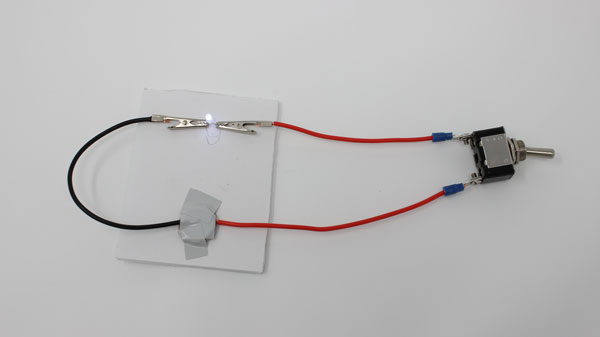
 Adding a Switch
- Insert the switch into your existing simple LED circuit so that electricity will have to flow through it for the circuit to be complete. It should look like the example above when completed.
How To: Prepare Spade Connectors
Follow along with this module to prepare wires with spade connectors
 16 AWG Wire
 1Wire Cutter / Stripper
 Spade Connectors
 Toggle Switch
 Phillips #2 Screwdriver


How To: Test Spade Connectors
Follow along with this module to test your spade connector's connection
How To: Attach Spade Connectors
Follow along with this module to attach the spade connectors to the switch


How To: Prepare Alligator Clips
Follow along with this module to create alligator clips
 Alligator Clip
 Wire
Wire
 Alligator Clip Crimper
 Wire Stripper


How To: Test Alligator Clips Connection
Follow along with this module to test your alligator clip's connection
Mini Project Adding a Switch (continuation)
 Adding a Switch
The main difference is that, instead of connecting the LED to the + side of the battery direction, the LED wire goes to one end of the switch, and the battery goes to the other. That is, the switch is "between" the battery and the LED.
Explanation
A switch is a mechanical device that moves a piece of conductive material so that it completes a circuit when it is in one position, and breaks the circuit when it is in another position.
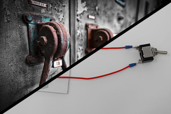
Old switches were literally a piece of metal that would be pressed down to connect circuits.
 Old Switches
This is why switches in a circuit diagram are typically illustrated as as a piece of wire that flips up and down to complete or break a circuit.
 Open and Closed Switch
This setup wasn't very safe (the full amount of electricity in the circuit would literally flow through the metal piece you were touching), and it was inconvenient to have to hold the switch in place. Modern switches are constructed using different materials and mechanical arrangements to accomplish the same thing, but more indirectly.
Old vs. New
When the switch is in the OFF position, no electricity flows through it, which means that there is not a complete electrical path through your setup. The LED does not light.
When the switch is ON, the electrical connection is complete, and the LED lights up.
Check Your Understanding
- Allow electricity to flow when it is in the ON position
- Allow electricity to flow when it is in the OFF position
- Prevent electricity from flowing when it is in the ON position
- Prevent electricity from flowing when it is in the OFF position
- Allow electricity to flow only in even increments
- To allow someone to easily power or de-power the circuit by hand
- To make the circuit conduct more electricity
- To allow the circuit to be turned off quickly in case of an emergency
- To allow the circuit to store energy and run even without the battery
- To allow the circuit to controlled remotely
Try It: Reverse Switch Direction
Does the direction of a switch matter?
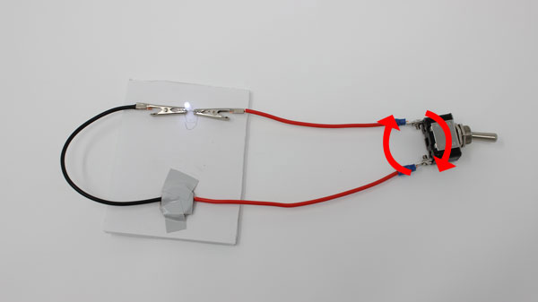 Try reversing the direction of the switch: swap which spade goes to which terminal on the switch.
Try It: Two Switches
Can you connect two switches in a row?
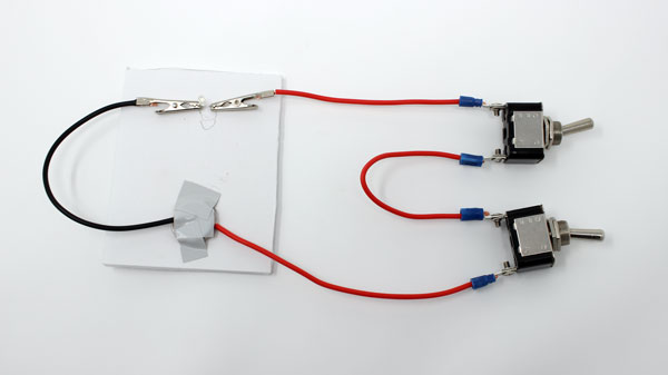 Wire a second switch into your circuit next to the first one, as shown above.
Other Types of Switches
The "simple" switch in this lesson is technically called a "Single pole, Single throw" (SPST) switch.
Other types of switches include Double Pole Switches and Double Throw Switches.
Double Pole Switches
- "Poles" are the number of circuits that are affected by the switch.
- Double pole switches are used to open or close two circuits at once.
- Flipping the switch connects both circuits (ON) or breaks them both (OFF) at the same time.
- Some switches have more than two poles, meaning they affect more than two circuits at the same time.
- EXAMPLE: Indicator Panel Lights: The switch controls a large, high power circuit. It also controls a status light in an instrument panel that says when the switch is ON. The light is small, and would be damaged if it were hooked up to the high energy circuit. A double-pole switch is used to flip both the main circuit and the small indicator light circuit together, without electrically connecting the two.
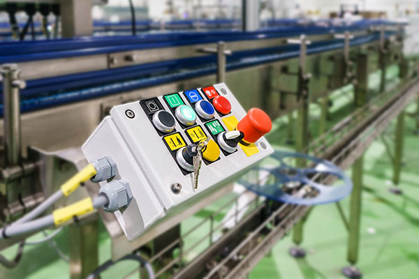 Indicator Panel Lights
Double Throw Switches
- "Throws" are the number of positions the switch has that complete a circuit.
- Double throw switches have two positions that complete circuits.
- Instead of switching between ON (open) and OFF (closed), the switch toggles between completing two different circuits.
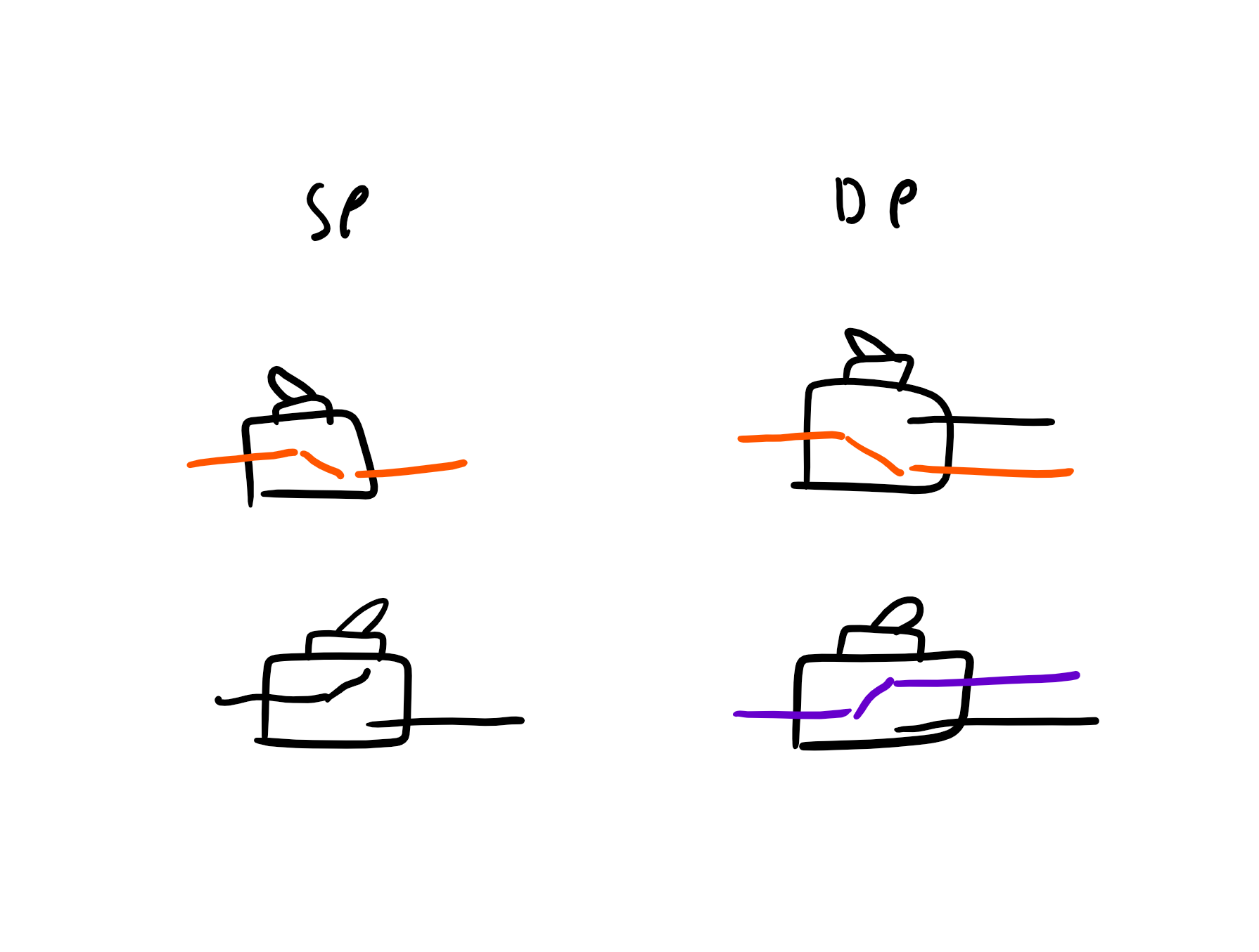 Poles and Throws
- A "double throw" switch can also have an OFF position that connects to none of the potential circuits.
- Some switches have more than two throws. For instance, a rotary switch can have many throws.
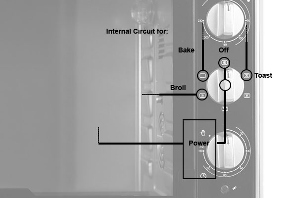 Toaster Over Switch
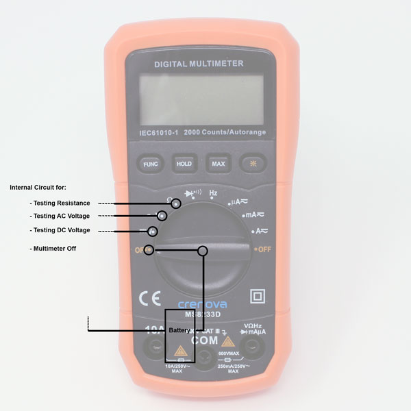
- EXAMPLE: Multimeter Dial: Each "function" on a multimeter is actually a different circuit. The dial on the front of the multimeter is a many-throw switch -- one for each function (plus OFF). When you turn the dial to a function, it powers the circuit for that function, and leaves the other circuits open.
 Toaster Over Switch
Complex Switches and Names
- Some switches connect multiple circuits, AND have multiple positions.
- "Single pole, single throw" = SPST
- "Single pole, double throw" = SPDT
- "Double pole, single throw" = DPST
- "Double pole, double throw" = DPDT
- "Triple pole, single throw = 3PST
- And so on...
How to Identify Switch
- Count the number of connections on the "left hand side" of the circuit diagram: how many circuits are opened or closed together when the switch is flipped. This is the number of poles.
- Count the number of connections on the "right hand side" of the circuit diagram for each pole: these are circuits that can be connected to, based on the position of the switch. This is the number of throws.
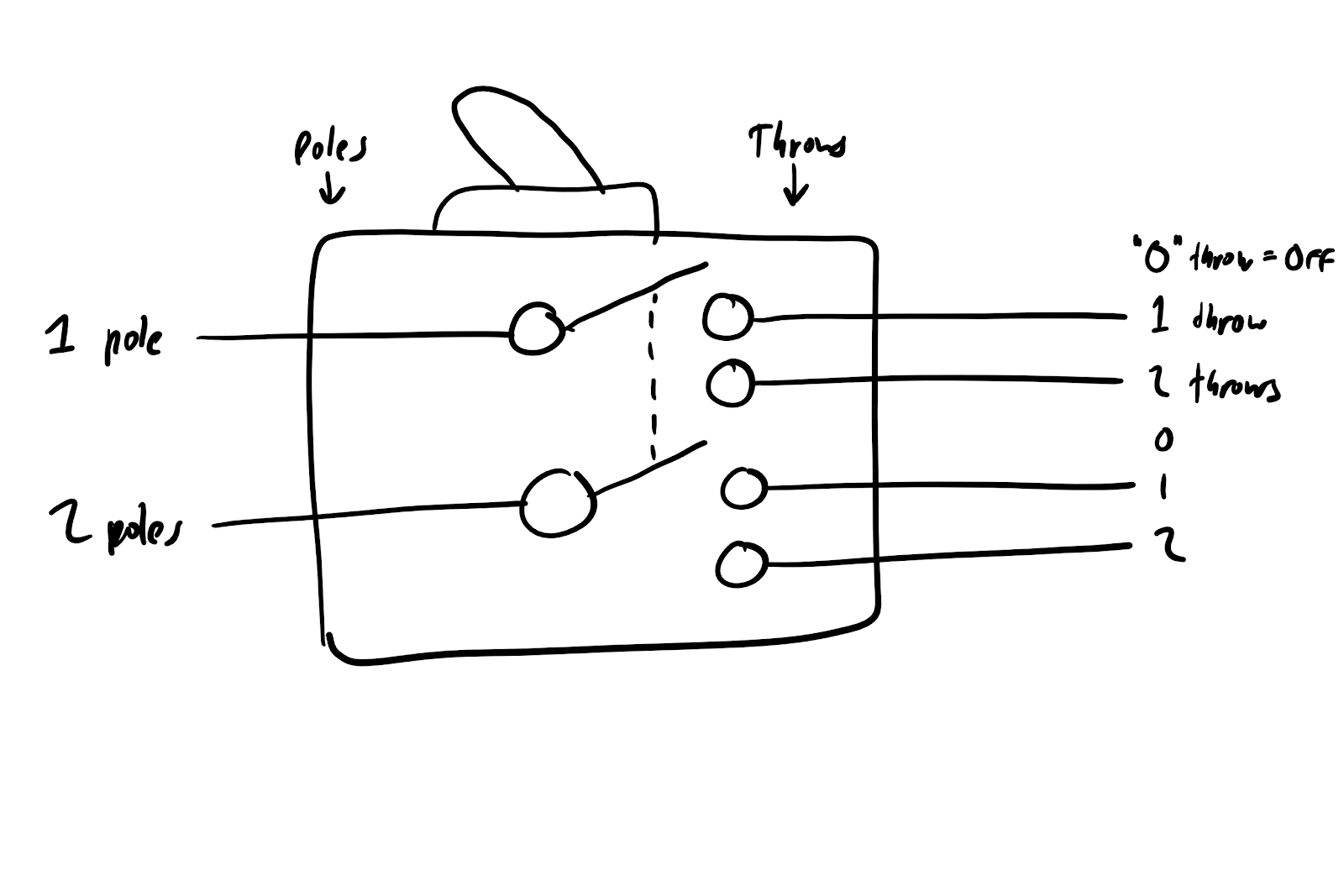 Poles and Throws