-
Controlling Signals (2019)
-
 Introduction: 2-Wheeled Cart
 -
Brain Powered
-
 Check Your Understanding: Brain Powered
 -
 Upload Photo: Header Pin Wires
 -
Sending Signals
-
Check Your Understanding: Sending Signals
-
 Upload Video: Blinking Circuit using Arduino Uno
 -
Faster Blinking
-
Relays: High and Low Signals (Part 1)
-
Check Your Understanding: High and Low Signals (Part 1)
-
Relays: High and Low Signals (Part 2)
-
Check Your Understanding: High and Low Signals (Part 2)
-
Upload Video: Powering a Motor using a Relay
-
Motor Control Boards
-
Check Your Understanding: Motor Control Boards
-
Upload Video: Powering a Motor using a Motor Control Board
-
Project: 2-Wheeled Cart
-
Upload Video: 2-Wheeled Cart
-
Upload Block Diagram: 2-Wheeled Cart
-
Brain Powered
Mini Project Brain Powered Circuit
In this project, you will take one of your LED circuits, and replace the battery with a robot microcontroller, sometimes referred to as a brain.
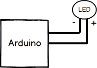 Block Diagram: Arduino connected to LED
Find the following components in your kit:
-
 A previously made circuit containing an LED
-
 Arduino Uno
-
 Computer with USB port
-
 USB A-to-B cord
-
 Multimeter
-
 22 AWG Wire
-
 Wire Cutter/Stripper
-
 Header Pin Crimper
-
 Male or Female Header Crimps
-
 Header pin housings or shells
-
Wire Stripper
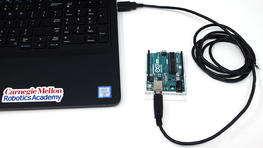
Take your USB cord and connect the Arduino Uno to a USB port on your computer. Power will be provided from your computer to the Arduino Uno.
Disconnect the wires that are connected to the battery (coin cell, rechargeable, etc.).
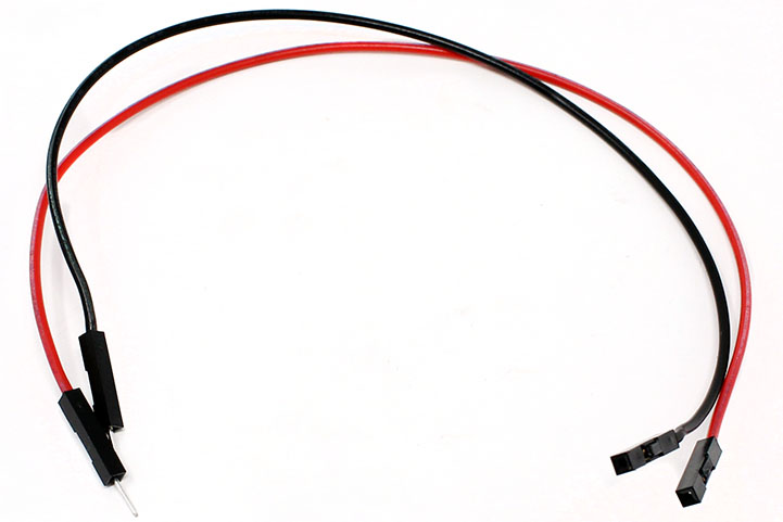
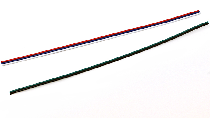
Attach male header pins to the one side of the wire and a female header pin on the other side. You will need to make 2 of these wires. Follow along with the module to create your wires.
To begin attaching and crimping spade connectors, you will need the following:
-
22 AWG Wire
-
Wire Cutter/Stripper
-
Header Pin Crimper
-
Male or Female Header Crimps
-
Header pin housings or shells
-
 Needle nose pliers or Wire Cutter / Stripper
You may want to have extra crimps and wires. These crimps are small, require a special crimping tool, precise techniques and practice to create a proper crimp.
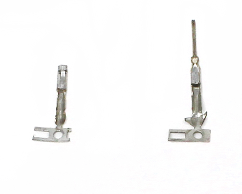
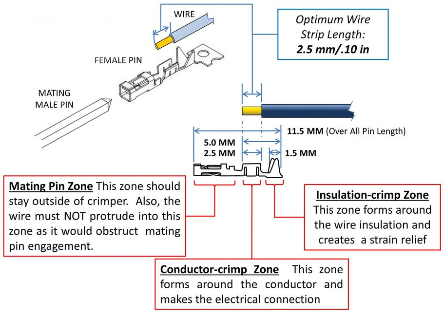
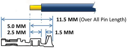
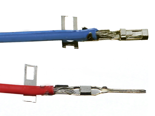
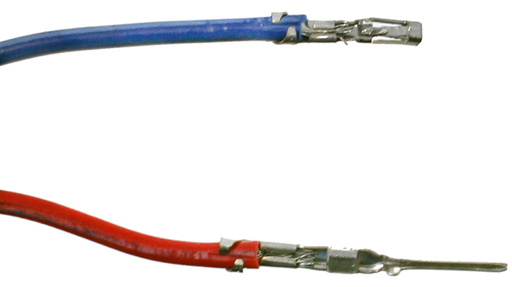
Header pin crimps are made up of three distinct portions: The mating pin zone is the portion of the crimp that interfaces with the component that you are connecting to. The other two portions interface with the wire. There is the conductor crimp zone which is the portion of the cimp that forms around the conductor and makes the electrical connection. The final part is the insulation crimp zone, where this part of the crimp forms around the wire’s insulation. This further securies the wire and creates a strain release. Both male and female header pins are crimped using the same process.
Cut a piece of the wire to the needed length and separate the number of wire you need from the .
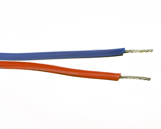
Strip the ends of the wire so that 0.10 in or 2.5 mm of wire is exposed. It may be easier to strip the wires longer and trim the exposed wires to 0.10 in or 2.5 mm.
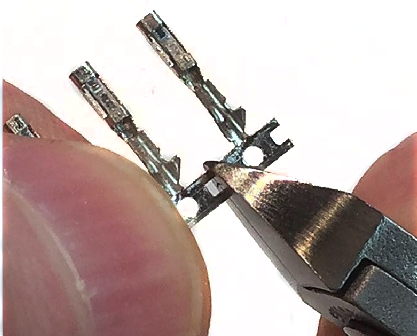
Cut off the male or female pin off of their connector strips. Keep the metal tab connected to the crimp, it will be used to align the crimp into the header pin crimper.
Place the wire into the crimp. Make sure the exposed wire is not in the mating pin zone.
To give your crimp a better chance to be successful use your wire cutters or needle nose pliers to start to fold over the tabs on the insulation crimp zone.
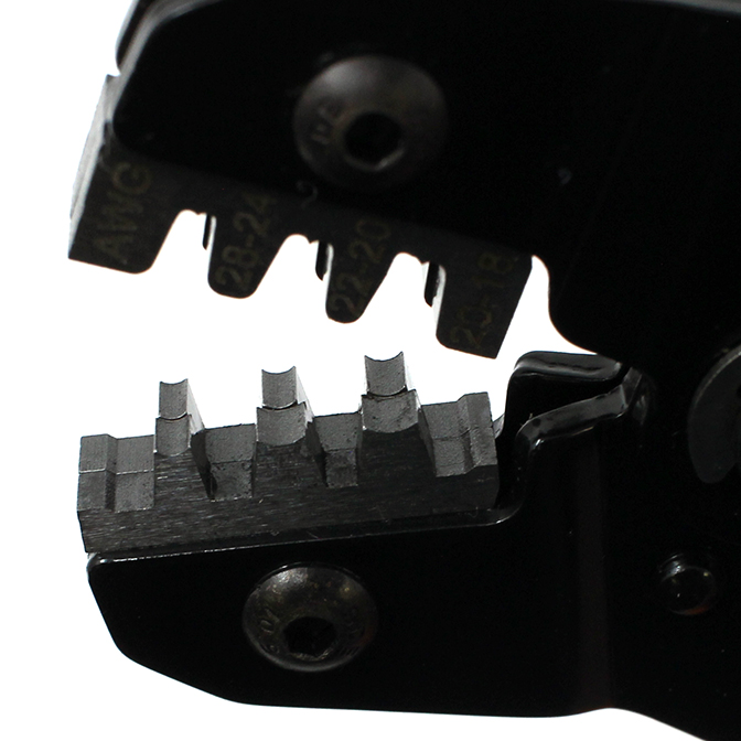
The recommended crimper has 2 different crimping areas the larger anvil crimps the insulation zone while the smaller anvil crimps the conductor zone. Make sure to line up the zones correctly or the crimp will not crimp properly.
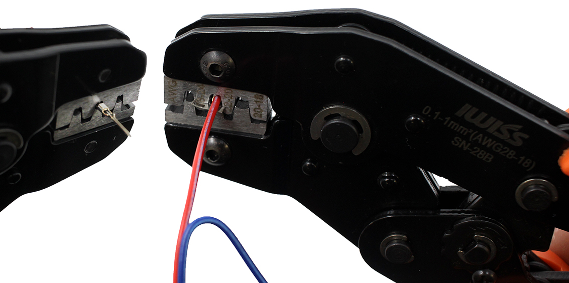
Use the crimping tool to crimp the conductor crimp zone and the insulation crimp zone. Make sure the Mating pin zone is extended completely out of the crimping tool. If you crimp this part it will deform and will not function
After crimping, if you inspect the connection and see that the crimped parts are not fully compressed onto the wire you may want to crimp the connection a second time.
Once the crimp is successfully attached to the wire you can remove the metal carrier strip by bending or cutting it off. After removing that, the crimp is ready to be placed into the plastic housing.
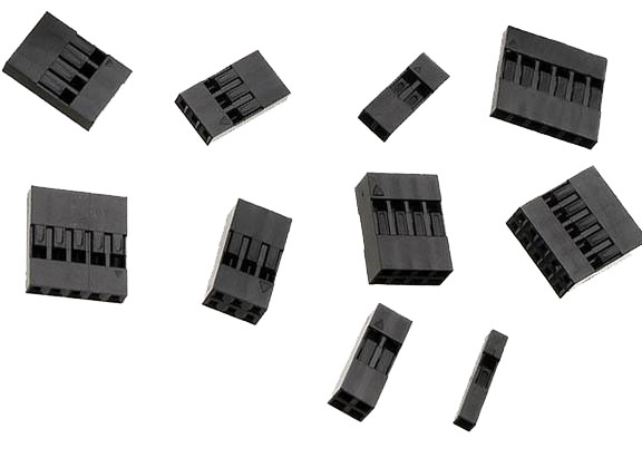
The plastic housing, or shields as they are sometimes called, add structure and support to make the crimp more durable. The plastic housings come in various sizes that can hold multiple connections in one block. Some projects will have all the connections next to each other which make the multi-connection block very convenient to use. Using single pin housing is easier to learn on and creates wires that have more flexibility in how they can be connected.
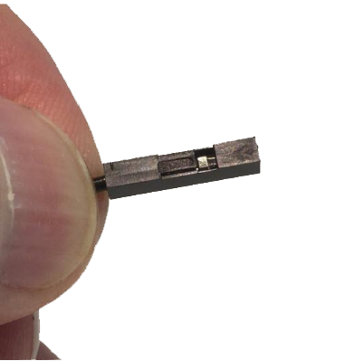
Both the male and female header pins have a small square or rectangle of metal in the pin mating zone. This metal “tab” will lock itself into the square opening or “slot” in the housing. Make sure the tab and the slot are facing the same direction and push the crimp into the larger opening in the housing. If done successfully the crimp will lock itself in the housing.

Perform a pull test to confirm that the crimp will not slip out of the housing. If the housing does not easly slip off you have successfully made a crimp!
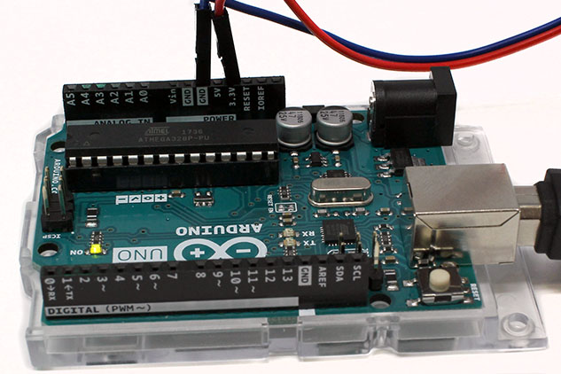
Connect the wires to the following two ports (GND and 3.3V) on the Arduino Uno. These two pins happen to be the “positive” and “negative” equivalent of a battery.
What happens?
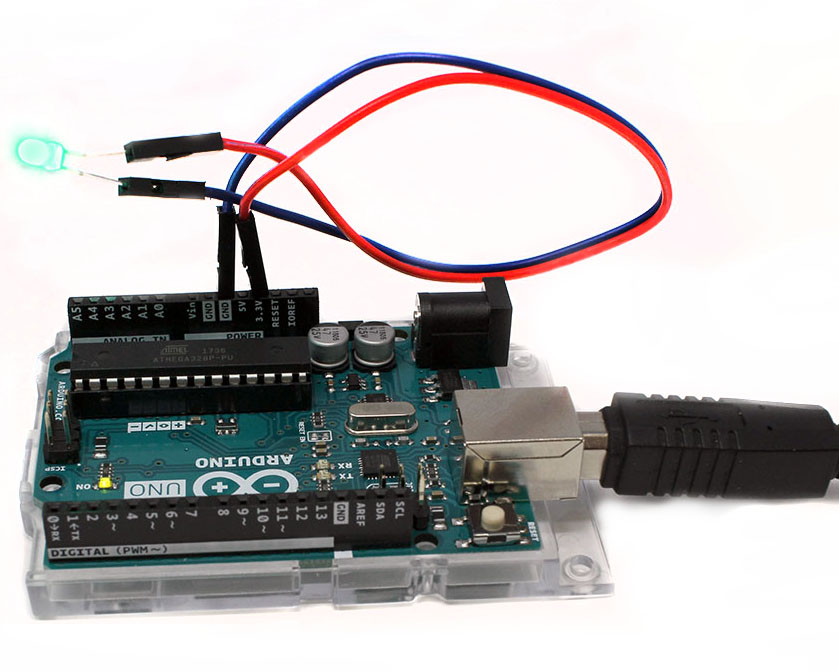
The circuit should now work just like when it was connected to a battery. If you have LEDs connected in the circuit, it may glow brighter due to the amount of voltage the header pins get.
Explanation
The ports that you connected the wires to are two of a whole set of ports that are available on the Arduino Uno. The "block" of pins are on what is called a Header, or more accurately, a GPIO Header. GPIO stands for General Purpose Input Output. This just means that the pins are available for general use.
Electronic Boards like the Arduino Uno usually come with diagrams that show what the different ports are. For instance, if you take a look at the diagram below, you can see what each of the ports are labeled:
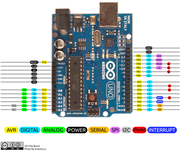
From this diagram, you can see that there is a section of “Power” ports. Some have a voltage labeled (3.3V, and 5V), and some say “Ground”. You can think of the Ground as the negative (-) terminals of a battery, and the ports like the 3.3V as the positive (+). When you connect a circuit to a Voltage and Ground port, it will provide the voltage needed to power your circuit.