-
Voltage: Parallel and Series Circuits (2019)
-
 1. Introduction: LED Sign
 -
2. Failed Series Circuit
-
 Check Your Understanding: Failed Series Circuit
 -
Mini-Project: Voltage Investigation
-
3. Parallel Circuits
-
 Upload a photo of a parallel circuit used to power multiple independent loads.
 -
Mini-Project - Shared Voltage Nodes
-
Check Your Understanding: Shared Voltage Nodes
-
Wire Coloring
-
Check Your Understanding: Parallel Circuits
-
4. Power Panels - Managing Parallel Circuits
-
Mini-Project: Mounting to the Terminal Block
-
Mini-Project - Terminal Block with Jumper
-
Check Your Understanding: Power Panels
-
Unit Project: LED Sign
-
Upload Photo: LED Sign
-
Upload Block Diagram: LED Sign
-
Voltage Investigation
Mini Challenge Voltage Investigation
To better understand the electrical 'push' called voltage let's take a step back to explore how voltage interacts with a properly functioning circuit.
Start by rebuilding the circuit with one LED in series with the battery
Follow along with the Voltage module to learn about the voltage settings on the multimeter and how to test the voltage in the circuit.
To begin testing wires, you will need the following:
-
 Digital Multimeter
Multimeters measure voltage differently for Direct Current (DC) Circuits and Alternating Current (AC) Circuits. On a multimeter these setting are shown with different symbols:


AC voltage can be very dangerous (especially the main voltage out of outlets on a building’s wall) and great care must be taken when measuring it with a multimeter. If you feel like you must test or measure AC, it is recommend you get a non-contact tester rather than use a digital multimeter.

Depending on the multimeter you have you may have one setting or many different settings for DC Voltage.

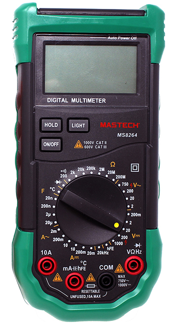
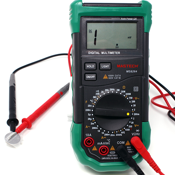


When measuring voltage make sure your probes are plugged into the correct ports. The Black Probe should be in "COM" or common and the Red Probe should be in the Red Port with the Voltage symbol (V)
When measuring voltage in a circuit it is always useful to know the voltage of your power supply, frequently with DC circuits this power supply is in the form of the battery.
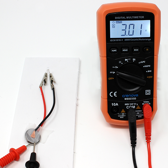

The multimeter can be used to test different parts of the circuit in a practice called nodal analysis. By measuring the voltage across the circuit, we can see how much voltage each component requires. In a very simple circuit such as an LED in series with a battery, the LED can be used to measure how much voltage the LED is using. This voltage is referred to as voltage drop.
Measuring the voltage drop of component in a circuit, requires the circuit to be connected. With the LED bright and lighting up probe both legs with the multimeter. (Place the red probe on the longer leg of the LED to measure positive numbers)
This LED is using 2.74 Volts of the available 3.01 Volt supply to illuminate.
Check Your Understanding


Explanation Properties of LEDs
With this new way of measuring voltage using the multimeter, we get an understanding of what an LED is and how it affects a circuit. Through the lessons up to this point, a few important properties of LED have been highlighted.
- The direction of the LED matters in a circuit.
- The LED requires a certain amount of voltage to allow it to create light.

What is an LED?
LED stands for Light Emitting Diode.
- Light Emitting - when a certain amount of voltage flows through the LED, it creates Light.
- Diode - A diode is a special electronics component that only allows electrons to flow in one direction. A common way to think about how a diode works is that a diode is a one way street for electrons. This property also explains why the LED must be connected in a certain direction for it to function in circuit.

A new property that all diodes have, including LEDs, is called “Forward Voltage”.
Forward Voltage can be thought as voltage require to allow voltage to flow forward through a diode. Plain diodes, (with out extra features like creating light) usually have a forward voltage between 0.3 Volts and 0.7 volts.
Since LEDs can be thought having two functions 1) being a diode and 2) emitting light, we can consider the LEDs forward voltage to require a small voltage to perform as a diode and a higher voltage to emit light. Since an LED’s main purpose is to create light, the forward voltage for the LED to create light is the number included in the LED’s Documentation.
Different Colored LEDs can have different forward voltages

Try It: Investigate your circuit
Recreate your original circuit with 2 LEDs so we can use the multimeter and our new knowledge about LEDs to understand what is happening in the circuit.

Measure the voltage drop across each LED to see if the LEDs are using any voltage. What did you find? Were your LEDs using any voltage? Were they using a very small amount?
Explanation What really happened?
What really happens to the extra 0.3 volts in the single-LED circuit?
It is technically not possible to have "extra" voltage in a circuit. When major components such as motors or LEDs do not account for all of the voltage in a system, the remainder is lost as heat in the other components. This includes wires, batteries, and other components which are not meant to heat up.
For this reason, most circuits include a resistor near the end. This is a component that conducts electricity, but not as well as a wire. These slightly restrictive components use up voltage when electricity passes through. This effect is used to get rid of the remaining voltage without heating up the wires and battery -- the resistor heats up instead of more sensitive components, plus the resistance itself causes the electricity to flow less freely and thus give off less heat.
In this lesson, we don't use a resistor. Instead, we rely on a special property of coin cell batteries, which is that they begin to act as resistors themselves if too much electrical current is flowing through the circuit. All batteries technically do this, but small coin cell batteries do it much more readily than larger batteries, making the circuits in this unit safe to learn and experiment with -- but remember that it is NOT safe to do this with higher-power circuits.